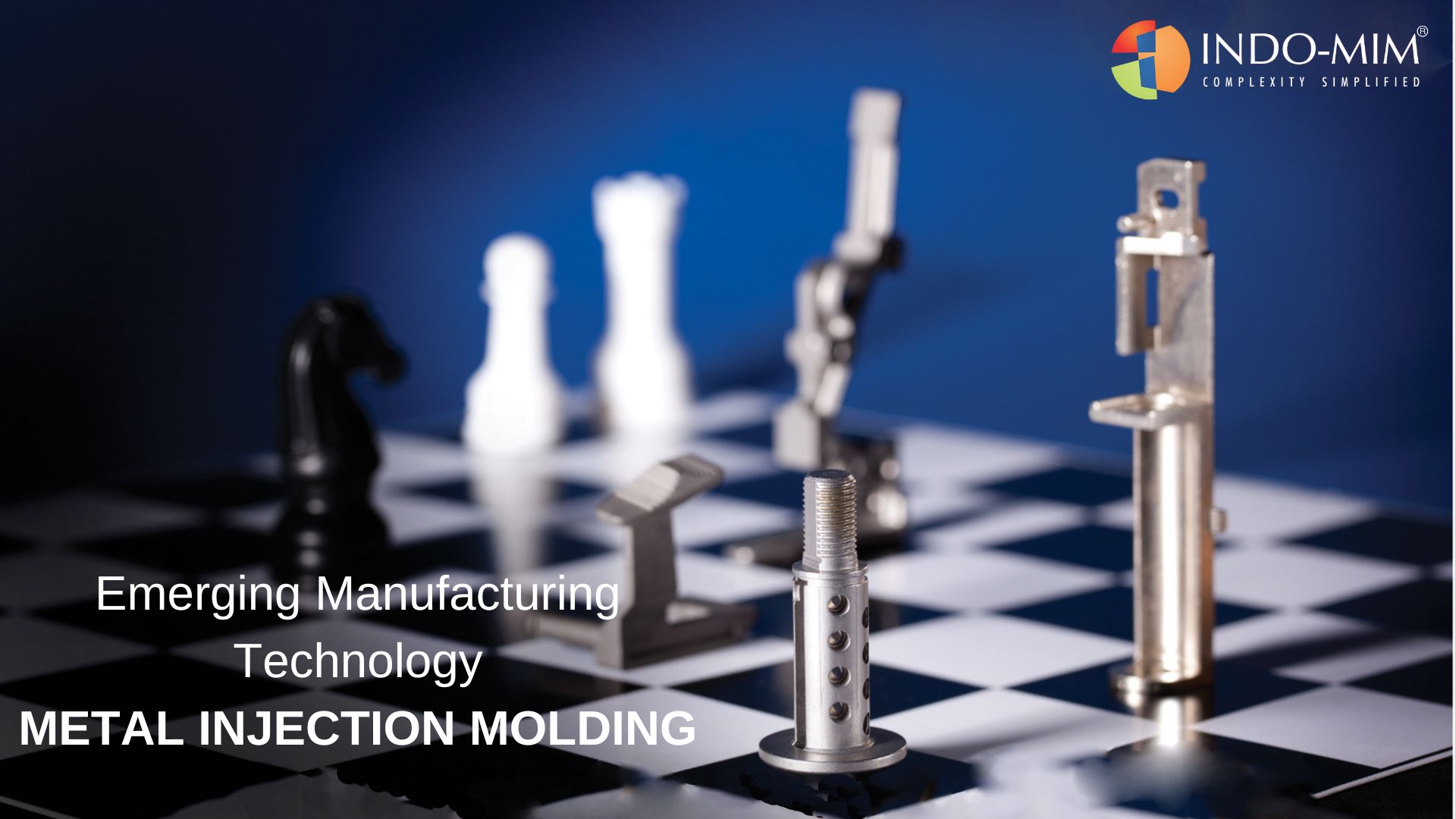
Metal Injection Moulding (MIM)
An Emerging Manufacturing Technology
Introduction
The process involves combining fine metal powders with plastic binders which allow the resulting metal powder and plastic mix referred as ‘ feedstock’ to be injected as a liquid into a hollow mold using equipment similar to standard plastic injection molding machines. After the part is cooled and de-molded, but before the plastic binding matrix is removed, the part is referred to as a ‘green part’. The next step is to remove the plastic binders from between the metal particles with the application of solvents and/or thermal processes. The resulting slightly porous metal part referred to as a ‘brown part’ is sintered at temperatures great enough to bind the surfaces of the particles to one another, but not enough to melt the metal outright. Sintered parts normally attain the densities of 96-98% of that of theoretical density.
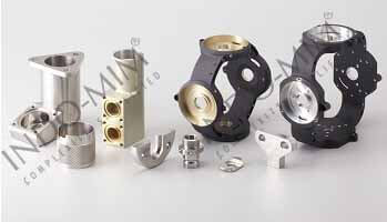
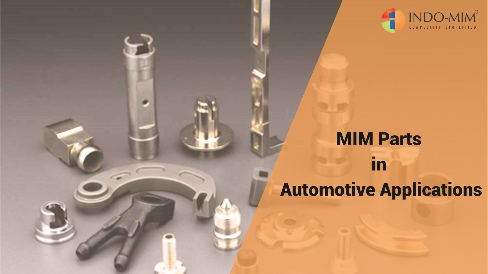
The MIM process is very similar to plastic injection molding and high-pressure die casting, and it can produce much the same shapes and configuration features. However, it is limited to relatively small, highly complex parts that otherwise would require extensive finish machining or assembly operations if made by any other conventional metal forming process.
The advantages of the metal injection molding process lie in its capability to produce mechanical properties nearly equivalent to wrought materials, while being a net-shape process technology with good dimensional tolerance control. Metal injection molded parts offer a nearly unlimited shape and geometric-feature capability, with high production rates through the use of multi-cavity tooling.
The limitation MIM is subject to is one of overall part size, with most components generally not exceeding 200 gm.
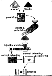
- Raw Material
Fine metal powder & polymer binders.
- Compounding
Fine metal powder is mixed with a polymer binder. This mixture is granulated to form “feedstock”.
- Molding
Feedstock is heated to form viscous slurry and injection molded to form “green” part.
- Debinding
Part of the binders are removed through solvent de-binding to get “brown” part.
- Sintering
The brown part is densified through sintering to get ‘finished’ part.

What can be a viable MIM part?
- High shape complexity
- Intricate parts difficult to machine
- Complex cross sections
- High strength & wear performance
- Require to achieve “close” tolerances
- Need to lower cost
- Medium to large volumes, annual production between 25,000 and 10 million pieces
Consider MIM for the parts which require –
- Discrete machining.
- Multiple secondary operations.
- Multi-piece assembly conversions.
- Unique material compositions
- Higher strength
- Complex geometry
- Part performance inadequate in case of PM, Die-casting or plastic
- Current process cannot handle large volumes
MIM Design Guidelines
- “Plastics mold design” principles apply
- Corner radii of greater than 0.3 mm
- Up to 2° draft on walls longer than 10 mm
- Minimum hole diameter 0.50 mm
- Min wall thickness 0.50 mm…..
- Max 5 mm (coring recommended beyond 5 mm)
- Gradual section thickness transitions
- Uniform wall thickness recommended as far as possible
- Stiffening ribs/ coring normally adopted
General Thumb Rule:
On a 10 mm dimension, a tolerance of +/-0.05 mm is possible
Design Advantages
- Flexible chemistry, close control on weight
- Hexagonal, square, splined, blind and flat bottom holes even at angles to each other feasible
- Co-molding /Sintering of two different materials possible
- Knurled features feasible
- External / internal threads feasible
- Logo / Part number / Raised letters / Impressions or Cavity ID can be done.